This appendix explains how to perform the following tasks:
Vapor control for VOCs can include environmental remediation, building mitigation measures, and institutional controls (ICs) to reduce or prevent VI from occurring. The management of vapors may be required at sites when the results of the site investigation phase indicate that indoor air concentrations of volatile compounds exceed mitigation screening levels in existing buildings or are likely to exceed screening levels in future buildings.
Environmental remediation refers to an action that reduces the threat by removing concentration or mass from the media that is affected, while mitigation generally refers to actions that prevent or minimize exposure from the affected media. When either action is required, a remedy or combination of remedies can be selected, implemented, operated, maintained, and monitored to control VI until the source of the vapors is eliminated.
ICs can take many forms, including restrictive covenants, zoning modifications, excavation prohibitions, and groundwater advisories. At undeveloped sites, or at sites where land use may change in the future, ICs may be necessary to ensure that the VI pathway is effectively addressed in the future. ICs can include mechanisms to require the preemptive installation of a vapor control technology or require further assessment. This practice avoids some of the difficulties associated with attempting to predict the potential for VI prior to building construction (because soil gas concentrations and distributions might change due to construction of the building).
Vapor control strategies, whether implemented as part of an ongoing environmental remediation or as part of a building specific mitigation, can be implemented as part of an emergency response action or to address longer-term exposure issues. The descriptions and details provided here focus mainly on the chronic exposure concerns and the investigation and design of an appropriate response. Though some of the technologies discussed below may be similar for emergency situations where the immediate and short-term health and safety of the building occupants is the primary concern, further consideration should determine whether the approach is an appropriate response action.
This appendix provides updates on the remedial and vapor control technologies originally identified in ITRC guidance Vapor Intrusion Pathway: A Practical Guideline (ITRC 2007) and has also been expanded to include new and additional technologies that may be appropriate for sites with PVI.
As identified above, vapor control technologies can include:
When actions are required, a remedy, IC, or combination of remedies can be selected, implemented, operated, maintained, and monitored to control VI until the source of the vapors is eliminated. In most cases, site-wide remedies and ICs are long-term solutions to VI, while building mitigation measures are short-term or interim remedies, implemented until the long-term or site-wide remedy is complete.
Interim actions typically are used to control or abate ongoing risk to human health or the environment in advance of final remedy selection. At some point during the course of an investigation, it may be determined that an interim remedial action is necessary due to the time necessary to complete the building vapor control design. For PVI, the interim response action may be the final response action or it may be a technology that can be effectively and rapidly implemented.
Reasons for taking an interim action may include the need for the following measures:
Site-wide remedies address the source contributing to vapors found in buildings, such as contaminated soil and groundwater, rather than controlling the entry of vapors into buildings. However, site-wide remedies may be sufficient in situations where the vapor concentrations in buildings are very low or where source remediation can be conducted very quickly.
Remediation of soil and groundwater contamination may include remedial technologies to reduce contaminant concentrations in site soils and soil gas, such as soil vapor extraction, or technologies that reduce concentrations in the groundwater, such as in situ bioremediation or multiphase extraction. For a remedial action to be protective for VI, exposures to vapors must be reduced and controlled until concentrations in the soil or groundwater reach acceptable levels. In general, source removal and soil vapor extraction site-wide remedies are likely to have the greatest potential to reduce or eliminate soil gas migration in the short term and, thus, preempt the need for interim control (such as institutional or building control) remedies. In cases where VI has been identified as an issue, the VI pathway must be effectively controlled in all potentially affected and inhabited structures.
Sites that may use a remedial technology to address a VI issue can be generally categorized into three groups:
Although site-wide remedies are not the focus of this document, numerous resources are available from ITRC and USEPA to provide assistance with selecting technologies and approaches associated with source control. These resources include (but are not limited to):
ICs are non-engineered instruments, such as administrative and legal controls, that help minimize the potential for human exposure to contamination and protect the integrity of the remedy. ICs typically play an important role in site remedies because they reduce exposure to contamination by limiting land or resource use, providing notifications to owner and a regulatory agency, and guiding human behavior at a site.
However, there are significant drawbacks to ICs that include:
In the event that site-wide remedies are not immediately effective in reducing or eliminating the potential for VI, or at undeveloped sites or at sites where land use may change in the future, ICs may be necessary to ensure that the VI pathway is effectively addressed. In most states, ICs can be put in place on either an interim or permanent basis to protect human health while the longer-term, site-wide remedies are being developed and implemented.
At undeveloped sites, or at sites where land use may change in the future, ICs may also be necessary to ensure that the VI pathway is effectively addressed in the future. Institutional controls at undeveloped sites caninclude mechanisms to require the preemptive installation of VI controls, such as subslab venting or depressurization systems, in new buildings. This approach avoids some of the difficulties associated with attempting to predict the potential for VI prior to building construction (because soil gas concentrations and distributions might change due to construction of the building). Installation and operation of fans, however, might not be required unless post-construction testing or other evaluations indicated a need.
ICs, like site-wide media remedies, are not the focus of this document. There are several guidance documents available that discuss the implementation of effective and reliable ICs and address the use of ICs as part of environmental remediation. The USEPA provides several documents on ICs (USEPA 2013n)
Building control technologies are typically required at VI sites (in both existing and new buildings) until long-term, site-wide remedies reduce soil and groundwater concentrations to acceptable levels. The following sections discuss various VI building control technologies, factors affecting technology selection, and common design and installation issues.
Several effective vapor control technologies may prevent the migration of vapors into a building and each have their advantages and disadvantages. One of the main considerations when evaluating each technology, however, is the long-term performance. CVOCs persist on site without active remediation of affected soil and groundwater. For these sites, the vapor control technology selected must operate over the long term or perhaps permanently. The exception to this practice is at VI sites with compounds associated with petroleum releases from underground storage tanks, where biodegradation can occur.
Table J-1 provides a summary of common building control technologies implemented for VI, which can be used as part of a remedial action. This table also provides a typical range of installed costs. However, because of various site conditions that affect the overall installation costs and material required, costs should be evaluated based on actual conditions (which may include additional costs associated withlead paint and asbestos abatement).
|
Technology |
Typical applications |
Challenges |
Range of installation costs (per ft2)(1) |
|---|---|---|---|
|
Active system |
|||
|
Subslab depressurization (SSD) |
Most structures; sumps, drain tiles, aerated floors, and block wall foundations may also be depressurized if present |
Low permeability and wet soils may limit performance, otherwise, highly effective systems; may require a discharge permit |
$2–$10/ft2; residential systems typically in the $2-4/ft2 range |
|
Subslab ventilation (SSV) or Crawl space venting |
New and existing structures relies more on influencing air flow over depressurization |
Low permeability and wet soils may limit performance, otherwise, highly effective systems; may require a discharge permit |
$2–$10/ft2; residential systems typically in the $2-4/ft2 range |
|
Submembrane depressurization (SMD) |
Existing structures, crawl spaces |
Sealing to foundation wall, pipe penetrations; membranes may be damaged by occupants or trades people accessing crawl space |
$1–$6/ft2; residential systems typically in the $1.50–$2/ft2 range |
|
Subslab pressurization (SSP) |
Same as SSD; most applicable to highly permeable soils |
Higher energy costs (not included) and less effective than SSD; potential for short-circuiting through cracks |
$1–$5/ft2 |
|
Building pressurization |
Commercial structures that are specifically designed |
Requires regular air balancing and maintenance; may not maintain positive pressure when building is unoccupied and may have high O&M costs |
$1–$15/ft2; heavily dependent on size and complexity of structure |
|
Passive barrier |
|||
|
Asphalt/latex membrane |
Typically limited to new construction prior to flooring being installed and crawl spaces; retrofitting a building is possible with the installation of an additional protective barrier |
Preventing tears and holes in the liner during installation; may not suffice as a stand-alone technology; must be chemically compatible with the COC |
$3–$7/ft2 for the system which includes liner costs of $2–$6/ft2 and a passive venting system cost of $0.75–$2/ft2 *see Note (2)
|
|
Thermoplastic liner |
Typically limited to new construction prior to flooring being installed and crawl spaces; retrofitting a building is possible with the installation of an additional protective barrier |
Preventing tears and holes in the liner during installation; may require seaming and taping; addressing subsurface penetrations; may not suffice as a stand-alone technology; limited vapor resistance testing available; may not suffice as a stand-alone technology |
$2–$7/ft2 for the system which includes liner costs of $0.50–$5/ft2 and a passive venting system cost of $0.75–$2/ft2 *see Note (2) |
|
Epoxy floor sealant system |
Retrofitting an existing structural slab in which a spray or roll is applied to seal floor surfaces |
Existing surface preparations (oil and grease free, level, competent); ensuring total or complete coverage; preventing tears, holes by building use; surface wearability and durability depending on application; may require subsurface venting as well as venting during placement |
$1–$7/ft2 cost varies on the amount of surface preparations and leveling required. System may also additional costs of a passive venting system cost ($0.75–$2/ft2) |
|
Passive Venting |
|||
|
Subslab venting; perforated pipe/low-profile vent and gravel layer |
New construction; existing construction would require additional surface protection |
Relies on advective flow of air due to wind and heat stack effects; does not continuously operate; air flows and suction typically far less than achieved by active systems; limited regulatory acceptance |
$0.75–$5/ft2 plus the additional cost of an engineered base consisting of sand or gravel |
|
Aerated flooring |
New construction, complete floor replacement, or floor overlays |
Relies on advective flow of air due to wind and heat stack effects to increase the oxygen; fans may require to achieve additional air flows and suctions; may not be effective for CVI |
New construction, $2–$2.75 /ft2 *see Note (2) |
|
Other |
|||
|
Indoor air treatment |
For marginal or low impacts, immediate response actions to address vapor (short term), and expected short time frames for a completed remedial action |
Typically generates a waste disposal stream; effective capture of air contaminants may be difficult; energy-intensive, with significant O&M burden |
Costs are highly variable dependent upon the building layout, the number of rooms, contaminant, concentration and overall size in addition to the type of technology employed. $15,000–$25,000 per application is typical for treatment of a single 2,000 ft2 area. |
|
Sealing the building envelope |
|
May not be effective over the long term |
$2.50–$6/ft2; cost varies depending on surface preparations |
|
Notes: (1) Costs for many of these technologies may be outside the ranges listed above due to many factors (such as regional contractor rates, regulatory review, access issues, and O&M). (2) Estimated costs do not include the cost of any required additional protective barriers or construction overlays ($2–$4 /ft2) not anticipated through normal construction practices. |
|||
Design Considerations
Passive barriers are materials or structures installed below or above a building foundation to physically block or limit the entry of vapors into a building. Passive barriers ideally cause soil gas that would otherwise enter the building under diffusion or pressure gradients to migrate beyond the building footprint. In reality, it may be difficult to completely prevent, or even substantially prevent, the entry of vapors into a building by passive barriers alone. Therefore, passive barriers are generally used in conjunction with passive venting. Any design of a passive barrier, however, should allow the venting system to be supplemented or upgraded to an active system or allow other measures to address inadequate performance. Many states require the use of either passive or active venting to enhance the efficiency of the barrier.
Most passive barriers consist of spray-on asphalt latex membranes, epoxy floor sealants, or low-permeability thermoplastic membranes. The design of a passive barrier should be supported by vapor diffusion coefficients, which assist in evaluating the liner's effectiveness for the site contaminants present. In new structures, barriers are typically installed after the utilities are in place and below the lowest level (prior to the floor slab being installed). In existing structures, membranes can be used to retard the intrusion of vapors in crawl spaces or over dirt floors; however, in most circumstances their use requires the installation of an additional protective layer, which will increase the installation costs of the liner.
Damage to Passive Barriers
To be effective, passive barriers must provide a complete barrier to vapor intrusion for the compounds of interest. Even small imperfections in the barriers (such as those due to holes, tears, or incomplete seals at the footings or pipe penetrations) may provide a significant migration route for soil gas. Even thicker (10–20 mil) membranes may be damaged during construction, particularly if placed below concrete slabs. The potential for punctures may be reduced by using thicker membranes. As a result some agencies have identified minimum liner thickness (EPA 2008a; Illinois 2013).
Passive barrier designs should include QA/QC plans to address the potential of damage to the membranes during installation, subsequent concrete pours, and building construction activities. It is also important that all future site activities include protocols for minimizing damage until a protective barrier (if necessary) has been installed. The QA/QC should also require thorough inspection of liner seals along all edges and at penetrations, observation during concrete pouring, and detailed procedures for testing the efficacy of the passive barrier after the slab is placed and (for example, pressure tests, smoke tests, and post-construction indoor air tests).
Refer to ASTM Standard E 1643-11 for more information regarding the use of water vapor barriers, although this standards is not sufficient to address the chemicals associated with VI and should not replace chemical specific diffusion testing. It is key when designing a passive barrier that the performance methods are identified and agreed upon by all parties.
Asphalt Latex Membrane
Key Elements of Asphalt Latex Membrane Systems
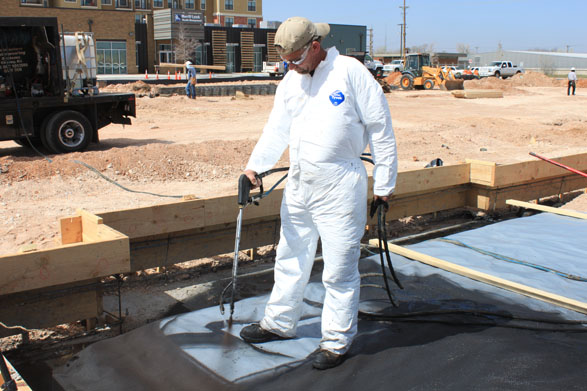
Most asphalt latex membranes are seamless, spray-applied, water-based membranes containing no VOCs, which provide a deterrent against VI. The membrane is typically installed prior to pouring the concrete slab and below-grade vertical walls in order to fully encapsulate the building footprint. The membrane is typically sprayed onto a carrier geosynthetic (geotextile or thermoplastic membrane).
Thickness measurements during the QA/QC process are critical to ensure proper performance of the installed membrane. The curing processes for these membranes highly depend on temperature, humidity, and convective air exchange rate surrounding the membrane. Care must be taken during the curing process to protect the membrane from punctures and damages. The potential for punctures may be reduced by using cushioning materials (geotextile or thermoplastic membrane) above the membrane and sand or fine-rounded gravel (pea gravel) below.
|
Advantages |
Disadvantages |
|---|---|
|
Low to moderate capital cost |
Even small holes can render the membrane ineffective |
|
Spray application should securely bond to most surfaces; eliminates mechanical fastening |
Likely not effective without venting |
|
Chemically resistant and adheres to the underside of the slab in case of soil settlement. |
Limited applications for existing structures that do not have subslab venting. |
Figure J‑1 Spray-applied membrane.
Source: Land Science Technologies, a division of REGENESIS.
The grade of latex (polychloroprene or styrene butadiene rubber) varies from manufacturer to manufacturer and the compatibility with the COCs and the potential for the product to off-gas should be assessed on a case-by-case basis.
Epoxy Floor Sealants
Key Elements of Epoxy Floor Sealant System
The epoxy floor sealant system is a vapor mitigation system that uses a chemically-resistant coating with a 100% solid epoxy blend. The system is designed to protect existing structures from VI without the need for additional concrete protection. Typical epoxy floor sealant systems can range between 10 to 60 mil and can be installed directly on top of an existing concrete slab. The epoxy floor sealant system is relatively new but appears to be effective, especially when used in conjunction with a passive venting system.
|
Advantages |
Disadvantages |
|---|---|
|
Can be applied to existing structures |
Extensive surface preparations required for proper adhesion |
|
Highly resistant to solvents, acids and caustics |
Susceptible to peeling and flaking off |
|
Low tensile strength can result in cracks; small holes, bubbles or cracks can render the barrier ineffective |
Epoxy floor sealant systems often require stringent surface preparation to ensure proper membrane-to-concrete adhesion. Any variation from the manufacturer’s specifications such as oil/grease, stains, moisture wicks, and other prior coats on concrete surfaces may cause the membrane to peel or flake off after installation.
Thermoplastic Liner
Key Elements of Passive Barrier Systems
A thermoplastic is a type of plastic made from polymer resins that become a homogenized liquid when heated and a solid when cooled. Though not a common application, when applied as a liner, a thermoplastic can be used as a passive barrier that can provide relevant resistive and diffusive properties to protect against COCs. Many of these liners, however, can be easily damaged during normal construction activities, even when cushioned by sand (ASTM E-1643- 11).
|
Advantages |
Disadvantages |
|---|---|
|
Low to moderate capital cost |
Even small holes can render ineffective |
|
No mechanical parts |
Likely not effective without venting |
|
Encapsulates the building footprint |
Limited applications for existing structures that do not have subslab venting. |
The potential for punctures may be reduced by using thicker membranes (for example, 60 to 100 mil HDPE or similar materials) and by using cushioning materials above or below the membrane, such as geotextiles, sand, or fine rounded gravel (pea gravel). No specific criteria, however, have been developed for thermoplastic liners, and some degree of imperfection (such as punctures or incomplete seals at seams and edges) should be expected in virtually all applications. In addition, ensure the chemical capability of the liner material with the COCs because of the potential for high concentrations of certain chemicals to adversely affect the membrane as well as the seams.
Key Elements of SSV
SSV systems or passive subslab venting involves the placement of a venting layer below the floor slab to allow soil gas to move laterally beyond the building footprint under natural diffusion gradients (resulting from the buildup of soil gas below the building) or pressure (thermal or wind-created) gradients. Generally, passive venting is only feasible in new construction because of the need to install an engineered base layer beneath the lowest flooring layer. There are several venting systems that can be assembled and installed, including perforated pipe and low-profile vents.
Passive subslab venting systems generally result in less depressurization and lower air flow exchange rates than active depressurization systems with fans (USEPA 1993). As a result, passive venting systems require more permeable venting media, more suction pits for a given building area, more distributed collection pipes, and tighter passive barriers than active venting systems. In addition, passive venting systems are typically not installed as stand-alone systems and require sealing or barriers such as those identified above in
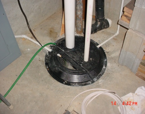
Figure J‑2. Passive sump mitigation system.
Source: Kansas Dept. of Health and Environment
|
Advantages |
Disadvantages |
|---|---|
|
Often applied when VI is possible, but has not occurred |
Not as effective as active venting systems |
|
Can be modified to an active venting system if designed accordingly |
Ambient temperatures and winds can adversely affect the success of this technique |
|
More applicable to new than existing buildings |
Not suitable for existing structures unless very modest concentration reductions required; active upgrades likely for new structures when large reductions in concentrations required (e.g., greater than about 90%) |
|
Lack of long-term costs from O&M as compared to active systems |
Some jurisdictions may not allow the use of passive venting systems for VI mitigation, and may prefer to go directly to active designs or use in combination with a passive barrier (see
Collection and riser pipes are generally a relatively small part of the overall cost. In general, passive venting systems cost more to install than active venting layers, for less reliable and consistent performance, in part due to the reliance on transmissivity of the venting layer and the integrity of the barrier layer in order to function. Nevertheless, passive venting systems, when they perform adequately, lack the long-term O&M costs of active system fans.
Key Elements of SSD Systems
SSD is a practical VI mitigation strategy suitable for most existing and new structures, including those with basement slabs or slab-on-grade foundations (USEPA1993). SSD systems function by creating a pressure differential across the slab that favors movement of indoor air into the subsurface. This movement is accomplished by pulling soil gases from beneath the slab and venting them to the atmosphere at a height well above the outdoor breathing zone and away from windows and air supply intakes. In new construction, SSD systems are similar to passive venting systems, except that a fan is used to draw soil gas through the subslab venting layer prior to discharging the soil gas to the atmosphere.
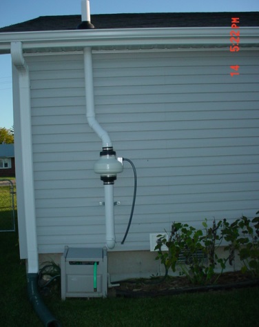
Figure J‑3. Active SSD system.
Source: Kansas DHE.
Active mitigation systems, including SSDs, are the most reliable, cost-effective, and efficient technique for controlling VI in the majority of cases, with concentration reductions in the 90 to 99% range expected (USEPA 1993), and 99.5% or greater in carefully designed and installed systems (Folkes 2002a). Subslab depressurization in the range of 0.025 to 0.035 inches H₂O is generally sufficient to maintain downward pressure gradients (USEPA 1993).
Hollow block wall or cinder block foundation walls may act as migration routes for vapor to enter homes, particularly if the holes in the top row of blocks are open. Therefore, mitigation techniques for block wall foundations include sealing the holes at the top, as well as depressurization of the block wall (USEPA 1993). Block wall depressurization is usually combined with subslab depressurization systems.
|
Advantages |
Disadvantages |
|---|---|
|
Successful track record of performance, 90 to 99% reductions typical, 99.5% or greater reductions possible with well-designed systems |
Requires periodic maintenance |
|
Adaptable technology, applicable to a wide variety of site conditions and geology |
Wet and low permeability soils retard soil gas movement, thereby limiting the overall suction field |
|
Simple gauges show whether the system is working or not |
Building-specific conditions may limit options for suction pit, riser pipe, and fan locations |
|
|
Need to assess the potential for back drafting of fireplaces and combustion appliances |
|
|
Limited or no performance during power outage or motor failure |
Although the fans for houses are low wattage and rarely require separate electrical circuits, the hook-ups are commonly installed by an electrician and usually require inspection before operation. Annual O&M costs for these systems are typically low. Commercial/industrial systems may use larger, more expensive blowers which consume more power. Often these blowers also require a separate 120 or 240 VAC circuit.
Key Elements of SMD Systems
SMD has been demonstrated to be the most effective mitigation method in crawl spaces, where a membrane is used as a surrogate for a slab to allow depressurization of the soil (USEPA 1993). Properly installed SMD systems have resulted in concentration reductions of up to 99.5%, similar to SSD systems (Folkes and Kurz 2002b). For SSD, an impermeable membrane is used to cover the exposed dirt surface of a crawl space while the depressurization system withdraws soil gas from beneath the membrane and prevents soil gas intrusion into the space above. Figure J-2 illustrates the application of this technology.
The membrane must be well-sealed along all edges of the foundation wall or footings, and to any pipe penetrations through the membrane, with enough slack to prevent tearing of the membrane under stress. Because many homes have furnaces or utilities in the crawl space, it may be necessary to place pads or other protective materials over the liner to allow access to the crawl space without damaging the membrane. Membranes can easily be damaged or lose their seal at the edges; therefore, periodic inspection of membranes (or other performance testing) is needed for SMDs.
Annual O&M costs for these systems are similar to that for SSD, though postmitigation monitoring, inspection, and repair costs may be higher.
|
Advantages |
Disadvantages |
|---|---|
|
Similar to SSDs |
Similar to SSDs |
|
Applied in situations (e.g., crawl spaces) where SSD is not practicable |
Membranes can be easily damaged and must be sealed well at edges to prevent leaks |
|
Can be combined with SSD |
System must be periodically inspected to confirm leaks are not present |
|
|
Performance may decrease during power outage or motor failure |
Key Elements of SSP
SSP systems are similar to SSD systems, except that fans are used to push air into the soil or venting layer below the slab, instead of pulling it out. This method increases the subslab air pressure above ambient levels, forcing soil gas from the subsurface to the sides of the building. USEPA (1993) suggests that this technology is most effective in highly permeable soils, where it may be difficult to pull enough air to depressurize the subslab region by SSD. SSP systems are applicable to both existing and new structures.
Cracks or openings in the slab or foundation walls can cause short-circuiting of the system and air forced below the slab may reenter the building, potentially pulling in some of the vapors that the system intended to keep out. Because indoor air is typically used to force air below the slab, fans should be equipped with a filter to prevent buildup of debris in the vent system. Other researchers (USEPA 1993) have observed that small pits at the discharge end of the vent system have improved performance of SSP systems. This approach, however, presents yet another design challenge associated with implementing this technology at an existing structure.
|
Advantages |
Disadvantages |
|---|---|
|
Does not require soil gas to be collected within structure |
More energy intensive than SSD |
|
May be more efficient than SSD in highly permeable soils
Potential for O2 to increase in the subsurface and encourage biodegradation when addressing PVI |
Cracks or slab openings may result in short-circuiting, leading to vapors inside structure |
|
May not be appropriate for tight soils
|
|
|
Performance may decrease during power outage or motor failure |
In some instances, it may be advantageous to positively pressurize the building interior (relative to the subslab), thereby preventing VI (Table J-9). The use of building pressurization typically requires that the building is designed especially to maintain a positive pressure within the envelope. It may be possible to tune the building’s existing HVAC system to achieve this positive pressurization; however this approach typically requires the installation of a new system and possible modification to the building structure. Warehouses and manufacturing facilities are not good candidates for positive pressurization.
The HVAC systems of many buildings operate during normal working hours and are shut off during the night and on weekends. In these cases, VI could occur while the systems are off, thus contaminating indoor air. The degree of the effect on indoor air quality during this time, and the length of time the effect persists after the HVAC system is restarted, must therefore be evaluated in determining the effectiveness of this method.
Additionally, make sure that soil gas is not simply deflected to adjacent, unprotected areas (for example, in a strip mall or multiunit commercial facility).
|
Advantages |
Disadvantages |
|---|---|
|
Can be applied equally well to both new and existing structures |
Generally more costly than other techniques |
|
May be the most effective technology for preventing VI |
Regular maintenance and air balancing needed to maintain consistent, positive pressure |
|
Not commonly an option for single-family residences |
|
|
|
Performance may decrease during power outage or motor failure |
Key Elements of Indoor Air Treatment
As an alternative to other forms of VI mitigation, air within the structure can also be directed to air pollution control equipment (such as carbon adsorption systems) to remove toxic air contaminants from the building interior (Table J-10). This technique is not widely practiced, since it encourages the collection of contaminant vapors within the structure and depends on the treatment system’s uninterrupted performance to protect receptors.
This approach can be an effective mitigation strategy, however, when combined with other techniques to control vapor concentrations in problem rooms, or when building materials have been affected by PHCs. Indoor air treatment is an alternative to whole building pressurization when subsurface depressurization or pressurization methods are not feasible (for example, when high water tables and wet soils are present). Indoor air treatment is generally only applied in existing buildings, since more cost effective systems can generally be installed in new buildings.
|
Advantages |
Disadvantages |
|---|---|
|
Results in the physical removal and disposal of the air contaminant, not simple redirection |
Less effective than other control methods (when applicable); zone of influence may be very small |
|
Less susceptible to malfunction or leaks than most other technologies |
Very maintenance intensive and costly to install and operate |
|
System leaks, should they occur, may result in higher exposures than no control |
Depending on the specific treatment method, there may be an ancillary waste stream, such as spent activated carbon, that requires disposal. In addition, to the extent treatment of air is required, it may be more advantageous to treat the air exhausted from another treatment technique (such as SSD) rather than to treat the indoor air of a structure. This advantage results from the smaller volumetric rate of air that would require treatment from SSD (which is smaller than the volume resulting if the entire indoor space required treatment).
Key Elements of Aerated Floor Systems
Aerated floors are concrete slabs with a continuous void space under the slab that can be used for subslab venting or depressurization in lieu of the sand or gravel venting layer commonly associated with traditional mitigation systems. Because the void space has very low resistance to air flow, vacuum levels and air exchange rates in the void space are generally higher and more uniform than in sand or gravel layers.
Aerated floors are typically constructed using proprietary plastic forms that are placed on the subgrade prior to pouring of the concrete slab. As a result, aerated floor systems are most applicable to new construction, although aerated floors can also be placed over existing slabs if a higher finished floor elevation can be accommodated. The total thickness of aerated floors (including both the void space and concrete) typically range from about 4 inches to several feet and are most commonly about 13 to 15 inches. The volume of concrete is similar to, or may be less than, the volume of concrete required for a traditional flat slab with the same load capacity.
|
Advantages |
Disadvantages |
|---|---|
|
Void space allows higher air flow rates for SSV and higher and more uniform vacuum levels for SSD than typical sand/gravel venting media |
Less applicable to existing buildings, unless replacing the existing floor slab or placement over the existing floor slab is acceptable |
|
Low-cost system due to elimination of gravel layer and liner. Concrete and steel costs may also be reduced. Made from recycled plastic (green product) |
Passive venting might not be sufficient when vapor concentrations are high and buildings are negatively pressurized (potentially requiring active venting) |
|
One small (e.g., 20W) fan can typically provide a relatively high and uniform vacuum across 20,000 sf or larger buildings |
Many architects, engineers, and contractors are not familiar with aerated floors, although this should change over time |
Aerated floors can be designed for SSV or SSD operation (in the former case, air inlets are typically provided to increase air flow rates) and operated in either active and passive venting modes, depending on the degree of venting or depressurization needed to control vapor intrusion. Note that aerated floors are not barrier systems, although the combination of the interlocking plastic forms, concrete, and caulking of joints and utility penetrations (consistent with radon industry standards) reduces the number of vapor entry points similar to barriers. As with all SSV and SSD venting systems, vapor intrusion is controlled primarily by removal and dilution of subslab vapors, depressurization and reversal of air flow direction across the slab, or both.
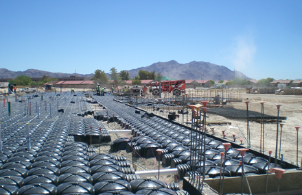
Figure J‑4. Cupolex aerated floor system.
Source: Vapor Mitigation Sciences, LLC.
A number of factors that are commonly identified during the course of a VI investigation and in completing a CSM may affect the choice of technology used to mitigate a particular building.
More mitigation options are typically available for new buildings than for existing buildings. In general, subsurface features such as passive barriers and venting layers cannot be installed below existing buildings, although depressurization technologies have been shown to work well in existing buildings without the benefit of these features. In addition, the presence of lead paint or asbestos may make more intrusive technologies less cost effective in older, existing buildings. On the other hand, new buildings may incorporate subslab venting layers, collection pipes, and vapor barriers (membranes) to enhance the performance of SSDs. These features may increase the efficiency of depressurization systems and reduce the number of suction points and fans required to achieve desired performance levels.
In some cases, these enhancements may be sufficient to allow effective use of passive mitigation systems, although passive system performance is case specific and should be critically evaluated during system design and verified during postmitigation diagnostic testing (see
If possible, mitigation should occur when the building is constructed, rather than as an add-on after it is constructed. Such decisions may confront property owners wishing to develop property where contaminated shallow groundwater or soil pose a potential threat to indoor air quality via VI. While the owner (hoping that no mitigation is needed) might choose to wait and test indoor air after the building is constructed, it is generally preferable for the owner and responsible parties to agree on building modifications during the design phase. Costs for the mitigation can then be minimized and better integrated with other building features.
The building size may have some effect on technology selection and system design, although in many cases larger buildings simply require larger systems, often with greater economies of scale. Larger commercial or industrial buildings, such as warehouses, may be less susceptible to poor indoor air quality resulting from PVI because of their larger building air volume, higher air exchange rates, open bay doors, positive air pressures (depending on HVAC system operation), and thicker floor slabs. These buildings, or portions of these buildings, therefore, may not require mitigation. But office areas with low ceilings and a number of dividing walls may have air exchange rates and volumes that are similar to residential homes. Therefore, when deciding what type of mitigation is best for the building of concern, consider which portions of the building the system must effectively mitigate.
In most cases, large buildings require multiple SSD suction points and either multiple in-line fans or one larger-sized blower. Multiple suction points can be connected to one larger fan or blower on the roof, using interior walls or columns to locate riser pipes. However, joints between slab sections, cracks, and other penetrations through the slab that are located between suction points should be sealed to prevent short-circuiting of the suction field.
Horizontal pipes may allow efficient depressurization and collection of soil gas over large areas below new building slabs. Horizontal pipes may also be drilled below existing large buildings, although the economies of this approach versus multiple suction points should be examined carefully. The potential impact of multiple horizontal drill holes on the foundation integrity of any shallow footings or weight-bearing slabs should also be considered.
The height of a structure can affect the technology selection and system design, especially for structures greater than three stories. Unlike the overall size of a building, which may simply require a larger system, the height of a structure may prevent certain technologies (such as passive venting) to be implemented. Often larger structures require additional engineering considerations for air flow.
Foundation types include basements, crawl spaces, slabs-on-grade, pier and beam, and any number of combinations of these basic types. Foundation type only affects design of mitigation systems that function by depressurizing soils below the building. SSD systems can be applied in any situation where a slab overlies soil, while SMD systems can be used in crawl spaces or anywhere that expanses of soil are exposed and future use of the area will not damage the membrane. Some buildings may require more than one vapor control technology.
Subslab features, such as grade beams, footings, and foundation walls may interrupt the development of suction fields below the slab, requiring installation of suction points in each area. In some cases, existing drain pipes and sump systems may be used as suction points—sealed and converted into efficient depressurization systems in existing residential and commercial/industrial buildings. In rare cases, heating and ventilation ducts may be present below the slab, providing a preferential pathway for PVI and short-circuiting subslab depressurization fields. Building-specific designs may be necessary to overcome this situation.
Certain building features, such as elevator shafts and sumps, may enhance the potential for VI unless they are properly sealed to prevent entry of both soil gas and groundwater containing PHCs. Elevator operations may enhance building depressurization and increase the rate of vapor entry into the building. Elevator shafts and other vertical conduits may also increase the movement of petroleum vapors throughout the building.
The foundation condition may also affect mitigation options. Excessive cracks, utility penetrations, or other openings may cause short-circuiting of the depressurization field, thus limiting the areal influence of a particular suction point. Solutions may include sealing of cracks and penetrations, and creating additional suction points for SSD systems. Fieldstone foundation walls may be too permeable for depressurization remedies to be effective without grouting or otherwise sealing the wall. In extreme cases, alternative mitigation strategies may be necessary, such as building pressurization or slab replacement.
The condition of the foundation wall may also affect mitigation techniques. Cinder block foundation walls may provide vapor migration routes through the interconnected voids in the blocks, particularly if the blocks are not sealed at the top of the wall. Mitigation strategies for such conditions include installation of suction points and depressurization of the wall, as well as sealing of the openings at the top of the wall. In some homes, dugout basements may have exposed earthen walls. These walls typically must be covered by membranes or walled off to allow effective operation of depressurization systems. Basements with exposed earth or rock floors may require placement of a concrete slab or false floor with a membrane to allow depressurization.
In some cases, crawl space areas are not accessible for installation of SMDs (
Foundation soil conditions may affect the design of depressurization systems. Low permeability soils, in the absence of a permeable venting layer below the slab, restrict the extent of suction fields, increasing the number of suction points required below slabs and membranes. In some cases high-vacuum/low-flow fans may be required. Larger voids or suction pits may also be sufficient to improve SSD system operation in tight soils (Folkes and Kurz 2002b).
Depressurization systems are generally effective in permeable soils; however, large venting layers may require low-vacuum/high-flow fans to move enough air through the system. Fan selection and pipe sizing guidance is available (USEPA 1993 and Fowler et al.1990). The mitigation contractor chosen for the project should have experience installing systems in the type of subsurface soils encountered below the buildings of concern. In permeable soils where depressurization is difficult, subslab pressurization may be more effective. In subslab pressurization, air is pumped into a permeable layer or natural soils below the slab to create positive subslab pressures that divert subsurface soil gas around the structure (see
Saturated soils may prevent effective depressurization of the subslab region by filling soil pores and making them unavailable for vapor transport. In cases where soils are damp but there is no continuing supply of water, air flow generated by an SSD system may dry the soils out sufficiently to allow effective depressurization. In cases where high water tables are controlled by drain tile or French drain systems, depressurization of the air space in the drain tile may be sufficient to control VI (see
If high water table conditions are episodic, which could be due to water infiltrating the ground after precipitation, then risk assessments may indicate that occasional loss of petroleum vapor control (due to loss of depressurization) does not result in a significant increase in long-term risk. Therefore, the SSD would only need to operate during low water table periods, when depressurization would be feasible. Alternatively, the SSD system can be augmented by a fan that either ventilates or pressurizes the basement with outside air whenever the sump pump kicks on, provided that flooding only occurs during warmer weather. If dewatering is not practicable, then basement or crawl space pressurization may be the most cost-effective method of petroleum vapor control. Pressurization, however, does not prevent direct partitioning of volatile compounds into the basement or crawl space air if water is entering the building. In these cases, it may be necessary to depressurize the basement or crawl space or to install a false floor above a slab or earth floor and create a thin venting layer that can be depressurized.
Sumps, footing, and other types of drains affect the design of the system. These features can directly affect the radius of influence. In addition, their presence may also provide a preferential pathway for vapors entering into a structure. A site-specific evaluation is required to addressing these features.
The COCs may affect mitigation system design in at least three ways. First, potentially combustible vapors (that may approach combustible concentrations) require intrinsically safe blowers and monitoring or alarm systems. Second, certain vapors may cause degradation of membranes, pipes, or the solvents used to join pipes. Third, the COC action levels, if any, affect the degree of concentration reduction required inside the building. Reductions of 80% or less may be possible with passive systems, while higher reductions generally require active depressurization or pressurization systems (USEPA 1993). Standard radon SSD and SMD systems generally perform well when reductions of up to 95% are required, while more rigorous attention to installation details, enlarged suction pits, and increased numbers of suction points and fans may be required for higher reductions (Folkes and Kurz 2002b).
The level of contamination present can affect the design of the vapor mitigation strategy. For example, passive barriers may require the use of products that are designed with higher diffusive rates and installed with additional passive vents. For active systems, the higher level of concentrations may also cause products to degrade a faster rate than designed.
In addition, some contaminants can be combustible if specific conditions exist. For compounds such as PHCs and methane, if the contaminant is found in concentrations between the lower explosive limit and the upper explosive limit, then an ignition source, such as an electrical spark, could cause a fire. Therefore, for sites that contain compounds near or within the explosive limits, the use of intrinsically safe equipment should be considered.
Explosive concentration ranges depend on the specific petroleum COC and should be considered when implementing a vapor control technology, especially for active venting layers and subslab pressurization (see
Methane generation by anaerobic biodegradation should also be considered. The lower explosive limit of methane is 5%; therefore, small amounts of methane can create explosive conditions.
The location of the vapor source plays a key role in the design of a mitigation system. If the source is located adjacent to the structure, then vapor control technologies may be implemented using features that prevent further on-site migration. On-site sources or sources located directly beneath a structure, however, require vapor control directly beneath a structure. A CSM that identifies the location of the vapor source can assist in identifying potential strategies based on the location of the vapor source.
The following sections discuss the general approach to design of building controls, pre- and post-diagnostic testing, and other design issues, including access, owner preferences, lead-based paint and asbestos, and back-drafting potential. As with factors that determine which mitigation method is used, there are design considerations and installation limitations that are common to the mitigation of all vapors.
Design of VI controls for new buildings should consider all of the factors discussed in the previous section. VI control requirements should be integrated into the overall building design process as soon as possible, since varying the locations of elevator shafts, basements, and even the building itself might help reduce the risk of VI. Foundations can be designed to enhance, rather than inhibit, suction field extension below slabs. Similarly, building pressurization systems can be optimized by designing tighter bottom floors and installing HVAC systems capable of creating and maintaining positive pressures during all seasons. VI control designs should include system layout drawings, minimum material specifications, installation procedures, construction quality control procedures, and post-installation testing procedures.
Design of VI mitigation systems in existing buildings should begin with a visual inspection of the building. For existing residential homes where SSD systems are applicable and the mitigation contractor is familiar with the houses in the area, this inspection is likely the only step required before installation (USEPA 1993; Folkes 2002a). For larger commercial buildings, or if subsurface or building characteristics indicate that an SSD system may not work well, pre-mitigation diagnostic testing may be required (see
For most existing residential homes, it is usually sufficient to install a relatively standard system without building-specific designs or pre-mitigation diagnostic tests, relying on the mitigation contractor’s experience in the area (USEPA 1993). While this “standard design” approach allows systems to be installed more quickly (which may be important at larger sites with many homes requiring mitigation), some form of postmitigation testing is required to verify that the standard design is adequate. Experience at the Redfield Site in Colorado indicated that only about 10% of homes requiring a 95% or less reduction in concentration needed adjustments after installation of a standard SSD system, and in most cases these adjustments were modest and inexpensive (Folkes 2002a).
For larger, more complex buildings or when visual inspections indicate SSD systems may not function well, it may be appropriate to conduct detailed diagnostic tests prior to mitigation and to prepare building-specific designs. Commercial building owners may only provide access if they can review the mitigation design before it is installed. Some states may also require approval of building-specific designs before installation. Designs may also be needed in order to apply for pre-installation permits or to provide the public opportunity for pre-implementation review and comment. Note that little guidance is available on the design and installation of mitigation systems for larger commercial buildings.
Both the standard design and custom design approaches are effective, but the best approach depends on site-specific circumstances, priorities, and to some extent, the preferences of the regulatory agency and the building owner. A summary of the advantages and disadvantages of each approach is shown in Table J-12.
|
Approach |
Advantages |
Disadvantages |
|---|---|---|
|
Detailed diagnostic testing and design followed by installation and testing |
|
|
|
Standard system installation based on experience and inspection, followed by testing and adjustments, if needed |
|
|
The need for air permits and exhaust gas controls for subsurface mitigation systems should be determined on a site-by-site basis, in compliance with applicable federal, state, or local air quality control regulations. Many states have a permitting program to implement the requirements of the federal Clean Air Act, as well as state-specific regulations. Typical permits include a Permit to Construct or a Permit to Operate. In some states, subsurface mitigation systems may be exempt from permitting requirements. Even exempt systems, however, may have a filing requirement. Filing may consist of a description of the emission source, the data necessary to estimate VOC emission, and information to determine whether the equipment is operating in compliance with local, state, and federal laws and regulations. As a part of permit maintenance, the state may require that VOC emissions be determined by USEPA, local state test methods, or both.
While the investigator and regulatory agency may be primarily concerned with the performance, cost effectiveness, and reliability of any mitigation system, the tenant in the building mitigated must live (or work) with the system and the owner of the building must maintain the value of the investment. The tenant and owner preferences for mitigation design features, therefore, should be taken into account.
Owners, tenants, and other parties (including contractors and architects) in the building process often have strong opinions about the aesthetic effects and inconvenience experienced. For example, if the mitigation contractor is considering an attic location for a fan, owners and tenants should be asked about the current and near-future use of that space. When there are multiple appropriate mitigation options available, the responsible party should be prepared to present the options that explain the advantages and disadvantages associated with each and also to describe why the preferred alternative should be the option installed.
When necessary, pre-mitigation tests can be conducted in existing buildings to measure the potential extent of the suction field for SSD systems. These tests, which are often referred to as “communication” or “suction field extension” tests, indicate whether SSD systems are viable, and aid in the selection of suction pit locations and fan size. The tests may also indicate whether any conditions (soil or building) exist that might preempt the use of active depressurization systems. The test typically involves applying suction to a centrally-located hole drilled through the floor slab (using a small portable vacuum or a portable radon fan) and observing the movement of smoke downward into construction joints or small holes drilled at locations surrounding, but distal to, the suction point. Digital micromanometers or other types of small differential pressure monitoring devices can also be used to assess the extent to which the suction system can achieve sufficient vacuum. Diagnostics should include testing under stressed conditions, such as during operation of furnaces and vent fans that tend to depressurize the building. In most cases, suction field extension tests are the only pre-mitigation diagnostic testing necessary prior to design and installation of SSD systems (USEPA 1993).
Suction field extension tests may also be conducted during installation of SSD systems, rather than prior to installation, using the first suction point to apply a vacuum and determine whether additional suction points (and larger fans) are required.
In many cases, mitigation contractors have sufficient experience with soil conditions and building types to accurately judge the size and locations of mitigation components. If many mitigation systems must be installed as quickly as possible, then it may be more expedient to install standard systems, test these systems as they are being installed and, when necessary, enhance or modify the systems to meet performance criteria (see
The passive VI mitigation system described in this section generally consists of a vapor barrier membrane that has been combined with a passive venting system. Unlike most active vapor control or mitigation systems, a passive barrier must demonstrate resistive properties against the COCs. Therefore chemical exposure and diffusion testing are pertinent when selecting the appropriate passive barrier. Other critical elements that must be incorporated into the design are protective barriers and a passive venting system.
New construction provides an opportunity to install a passive mitigation system, since the system can be easily incorporated into the design process. In most new construction design using passive barriers, the protective layer consists of the placement of cement and other flooring material planned as part of the building design. However, if a structure will be retrofitted with a liner on top of existing flooring, depending on the barrier used, an additional protective layer may be installed (except when using some of the newer epoxy floor sealant systems).
Passive venting is a critical component of any passive mitigation system and prevents the diffusion of contamination across the barrier. Therefore, it is common practice (and a requirement in most states) to incorporate relatively inexpensive ventilation piping and wind-driven ventilators. The design of the venting system should also allow for the conversion of the passive system to an active system if needed. The actual design and layout of the piping system should be based on soil types as well the expected concentrations of vapors expected. The piping sizes and locations should be sufficient to remove any vapors generated by the source material.
To aid the in the design and the selection of an appropriate liner, the diffusion coefficient of a passive barrier can be incorporated into a J&E model to assess the design performance. One method includes using a three-phase model, which allows permeabilities to be entered from different horizons. To account for the barrier, the diffusion coefficient for the contaminant is substituted in place of one the soil layers. The three phase model is available from the USEPA Waste and Cleanup Risk Assessment website (USEPA 2005c).
A mitigation system barrier can also be considered when other mitigation methods are difficult to implement, such as for low permeability soils or shallow groundwater beneath the floor slab. In these cases, it is difficult to obtain adequate vacuum fields for active mitigation systems. Installation specifications for barriers should follow the manufacturer’s guidelines. It is also critical that a construction QA/QC plan be developed and followed during installation to ensure that the installation meets the design specifications, because most passive barriers will be inaccessible upon completion of the building. Most construction QA/QCs include visual inspection, thickness testing, smoke testing, detailed records of the amount of material used, and photographic evidence. Geomembrane barriers that are dual-track welded should be channel pressure tested. Spray-applied membranes should be allowed to cure sufficiently (typically overnight), then thickness tested with a blunt-nosed thickness gauge or by cutting specimens every 500 ft2.
If the performance of the passive barrier will be evaluated using the collection of samples above the liner, then sampling ports should also be incorporated into the design so that contamination both above and below the liner can be compared.
When necessary, pre-mitigation tests can be conducted in existing buildings to measure the potential extent of the suction field for SSD systems. These tests, which are often referred to as “communication” or “suction field extension” tests, indicate whether SSD systems are viable and aid in the selection of suction pit locations and fan size. The tests may also indicate whether any conditions (soil or building) exist that might preempt the use of active depressurization systems. Tests typically involve applying suction to a centrally-located hole drilled through the floor slab (using a shop vac or a portable radon fan) and observing the movement of smoke downward into construction joints or small holes drilled at locations surrounding, but distal to, the suction point. Digital micromanometers or other types of small differential pressure monitoring devices can also be used to assess the extent to which the suction system can achieve sufficient vacuum. Diagnostics should include testing under stressed conditions, such as during operation of furnaces and vent fans that tend to depressurize the building. In most cases, suction field extension tests are the only pre-mitigation diagnostic testing necessary prior to design and installation of SSD systems (USEPA 1993).
Suction field extension tests may also be conducted during installation of SSD systems, rather than prior to installation, using the first suction point to apply a vacuum and determine whether additional suction points (and larger fans) are required.
In many cases, mitigation contractors have sufficient experience with soil conditions and building types to accurately judge the size and locations of mitigation components. If many mitigation systems must be installed as quickly as possible, it may be more expedient to install standard systems, test these systems as they are being installed and, when necessary, enhance or modify the systems to meet performance criteria (see
Whether the structure to be mitigated is a commercial or institutional structure, or a private residence, arranging for access to the property can prove difficult. Commercial building tenants may not want construction activities disrupting business operations, and some homeowners may resist granting access to their home for a variety of reasons, including privacy issues. Scheduling indoor tests may also be difficult, since access is required for both placing canisters and picking them up 24 hours later. Homeowners often want to schedule tests before or after work. To address these concerns, it is best to develop and execute an access agreement between the property owner and the investigating/mitigating entity.
Depending on the age of the structure being investigated, other environmental hazards such as lead-based paint or asbestos may be present and can potentially delay mitigation activities. Generally, structures built before 1990 may pose a hazard with respect to lead-based paint, while asbestos may be present in buildings built before 1980.
The presence of one or more of these materials may delay construction activities within the structure until the hazard is adequately addressed or the appropriate safeguards are in place. Addressing these hazards adds to the cost of mitigation and may negatively affect the overall project schedule.
When one or more ventilation techniques are used to address VI, these systems affect the overall balance of air flow within the structure. If the ventilation equipment and combustion devices within a structure (such as furnaces, wood stoves, clothes dryers, and water heaters) are not properly balanced, then exhaust gases from the combustion units may collect within the structure. This situation is often referred to as “back-drafting” or “spillage.”
In buildings with natural draft combustion equipment, a back-draft test may be indicated prior to installation of mitigation systems involving active ventilation (such as SSD). If back-drafting is occurring, it should be corrected prior to installation to avoid safety hazards.
Most residential mitigation activities using pressurization and ventilation techniques add little to the potential for overall building depressurization. Typically, SSD fans operate at low flow rates and induce a minimum pressure differential across the slab. SSD systems should be installed by experienced contractors familiar with the potential for and prevention of back-drafting of combustion equipment (for example, water heaters or furnaces).
Although typically required by building codes in newer homes, older homes may not have cold (outside) air-supply vents for gas furnaces or water heaters, resulting in greater negative pressures when furnaces turn on and greater potential for both back-drafting and VI. In some cases, providing cold-air vents alone may mitigate minor VI problems and, in all cases, should enhance the performance of SSD systems. Although not currently required of radon contractors, USEPA has recommended (USEPA 1993) that procedures be undertaken to investigate the possibility of back-drafting.
Depending upon the size of the building and the number of system fans/pumps needed, system piping limitations for delivery or extraction of air must be considered. Vent risers should be in a location that can be properly secured for protection against damage and should terminate at a minimum of two feet above the roof of the structure, while also a minimum of 10 feet away from any window or air intake into the building. The diameter of the vent riser should be appropriate for the capacity of the system and meet any local building or fire codes.
Other things to consider for venting include overall height of the structure (see
Because the reduction goals must be met consistently over long periods of time, reliability is an important criterion for selecting vapor control technologies. While most of these technologies are considered mature and have been used extensively for other applications such as radon or moisture control, confirm system reliability with the vendor or consulting engineer.
An aerobic biodegradation zone (see Figure 2-1) is typically present along the perimeter of the PHC plumes in groundwater and soil gas. Within this bioactive zone, natural microbial activity can degrade many PHCs into nontoxic end products such as carbon dioxide, water, and methane. If PHC concentrations are high enough, available oxygen may be depleted, which in turn limits aerobic biodegradation. When oxygen is limited, anaerobic biodegradation of LNAPL or other organic sources can produce methane. Significant anaerobic biodegradation and methane generation can occur in some situations within anoxic zones of the plume interior and adjacent to the LNAPL source. Methane readily biodegrades under aerobic conditions and, when present, creates an additional oxygen demand. Methane also creates an explosion hazard if it accumulates within confined spaces (such as utility vaults and passages, basements, or garages) in high concentrations and there is sufficient oxygen and a source of ignition.
Methane may be more significant at sites where large volumes of ethanol-blended gasoline (and higher ethanol content fuels) have been released into the subsurface. As the ethanol content increases, so does the potential for creating methane. Methane production can increase soil gas volume and pressures and result in advective soil gas flow toward receptors. Petroleum vapors may also migrate with the methane. In addition, aerobic biodegradation of methane may deplete oxygen that otherwise could be used for biodegradation of the PHC contaminants. Moreover, in situations where intrusion of methane into confined spaces results in the accumulation of very high concentrations, there can be a risk of explosion.
Intrinsically safe equipment is defined as “equipment and wiring which is incapable of releasing sufficient electrical or thermal energy under normal or abnormal conditions to cause ignition of a specific hazardous atmospheric mixture in its most easily ignited concentration" (ANSI 2003). This condition is achieved by limiting the power available to (and used or generated by) the electrical equipment in the hazardous area to a level below that which will ignite the hazardous atmosphere.
When methane or other contaminants that may obtain or reach explosive conditions are present, ensure that the electrical components are intrinsically safe. Although methane generated by degradation of PHCs is not under pressure and is unlikely to produce an explosive environment, there is the potential for an active mitigation system to pull in methane, which can come into direct contact with the electrical components.
Performance criteria provide benchmarks for measuring whether the vapor control technology is meeting objectives and provide a reasonable indication of whether the system is operating as specified. The primary performance metric for a vapor control technology is acceptable levels of contaminants in indoor air; however, indoor air samples may be avoided in some situations through the collection and assessment of indirect performance indicators. Environmental professionals, however, may need to determine percent reduction in measured contaminant concentrations in indoor air resulting from the engineered system or barrier in order to assess the systems effectiveness.
Performance criteria for a vapor control technology should be include a specified time frame that depends in part on the risk to the occupants. In addition, it is critical that the performance criteria undergo constant evaluation to determine whether they are meeting the overall project objectives. Note that often more than one performance criteria may be applicable for a specific type or design of a mitigation system.
Indoor air sampling for the COCs is generally the most direct method to determine whether exposures have been controlled by the mitigation system. Because of the possibility of significant background sources for PHCs, indoor air sampling should be paired with ambient air sampling, as well as with updated chemical inventories. Indoor air samples should be collected from the lowest potentially occupied space. In situations where there are separate types of mitigation systems (such as rooms over crawl spaces with membranes, versus rooms over a concrete slab with an SSD) samples should be collected over each area. For large buildings, with multiple air handling systems, samples should be collected from each distinct HVAC zone.
In buildings, COCs may not be distributed uniformly in space and time. Thus, the sampling plan must consider the locations, number, and frequency of samples. Sample placement and duration are frequently selected to meet risk-assessment-related requirements. Durations over which to collect an air sample are established by the local or state agency (for example, 24 hours for residential scenarios). The air within relatively open zones (such as auditoriums, reception areas, and living spaces of residential buildings) that have nearly uniform temperatures can be expected to have contaminants well mixed within the zone. Measured variations within such zones are often comparable to the observed variations of duplicate measurements. Short-term spatial variations are usually small compared to temporal variations on daily and seasonal scales. When a complex building is being evaluated, it is typically represented by a conceptual model consisting of a group of interacting zones. Parts of the building with separate air-handling systems or built using different construction methods are considered as independent zones.
During mitigation, subslab measurements during the operation of a vapor control technology can provide direct and indirect information on whether they system is effective in preventing VI.
The collection of subslab samples is not always performed; however, when it is collected, the data can be valuable for several purposes. Decreasing concentrations can indicate that a stepped mitigation approach may be considered (to prevent constant fan operation) or indicate that vapor concentrations have decreased due to a remedial action or through biodegradation and VI is no longer an issue.
Evaluations typically require multiple sampling events to account for expected sampling variability. Detailed instructions for installation of subslab sampling probes are provided in several documents (for example, USEPA 2006a, NYSDOH 2006b, NJDEP 2005, and MADEP 2002a).
CO2, CH4, and O2 are key parameters typically monitored to document that biodegradation is occurring. Generally when O2 is present at concentrations at 5% or greater, aerobic conditions are known to exist, and the microorganisms consume all available PHCs. This aerobic biodegradation can occur relatively quickly, with degradation half lives as short as hours or days under some conditions (DeVaull 2007). Some PHCs can also biodegrade under anaerobic conditions; however, this process is less important and generally much slower than aerobic biodegradation. Documenting the levels of CO2, CH4, and O2 can provide evidence that site conditions prevent PVI from occurring.
For subslab depressurization systems or for HVAC systems designed to create positive building pressures, performance can be verified by measuring pressure differentials across the slab (typically with a micromanometer). In some situations, the pressure differential across the basement walls is also critical. Pressure differential readings should be collected at a sufficient distance from a subslab depressurization suction point to reflect the pressure field extension to distal portions of the slab. Where subslab obstructions are present, differential pressure measurements should be taken on either side of such obstructions. Locations for pressure measurements should extend to the extremes of the slab.
A micromanometer should be used to measure pressure differentials at measurement points (NYSDOH 2006b). If the pressure field extension cannot be quantified with a micromanometer, then the performance of the mitigation system may be in question. Typical measurements should be collected as 5 to 10 second averages. Guidelines for adequate subslab differential pressure vary by state, with values of 0.004 inches of water column considered acceptable in some states (New York and New Jersey), while ASTM and Massachusetts recommend a minimum value of 0.01 inches water column. In order to achieve the highest reliability, the micromanometer should undergo annual calibration.
Smoke testing is a qualitative method of tracer testing that can be used to detect leaks or preferential migration pathways, or to test airflow patterns of an SSD. A smoke tube or smoke stick, which emits a visible stream of smoke, can be used to test for leakage through pipe joints and slab-wall junctions. In general, leak testing of pipe joints is more effective if smoke is injected into the pipe under pressure. Smoke testing for membrane applications can be used to test for leaks at the seams and seals of membranes. This testing can also be used at cracks and joints in a slab and at suction points in SSD systems.
The reliability of smoke testing for small leaks has been questioned. Quantitative methods have been recommended in place of smoke testing, such as tracer testing and differential pressure instruments. The concept of using a tracer gas to verify the integrity of a subslab membrane is similar to that for leak testing a subslab or soil gas sample port. When using a tracer gas to detect leaks in a membrane, the tracer gas is typically injected under the membrane, and the atmosphere above the membrane is monitored for the tracer gas by sweeping a detector probe across the entire membrane area. Tracer gases typically used include helium or sulfur hexafluoride. Helium and sulfur hexafluoride specific detectors are readily available; however, be mindful of the response time for the detector being used and adjust the rate at which the detector probe is swept across the membrane accordingly. Depending on the construction methods used and how the membrane is attached to the foundation, tracer gas detections may occur around the perimeter of the membrane.
The use of passive barriers often requires unique performance criteria that are either met or evaluated during the design and monitored during the installation. In order to effectively design a passive barrier, a manufacturer must be able to provide testing that documents the effective diffusivity for the COC. The effective diffusivity based on the estimated or expected concentrations establishes the thickness requirements necessary to limit the flux of contaminants into a structure. As part of this procedure, the installation documentation is critical to ensure that the design specifications are met. Testing procedures, such as pressure differential and smoke testing, often assist in evaluating the installation.
There may be other diagnostic tools or testing procedures that may be used to document that the installed vapor control technology is functioning as intended. The method used should be appropriate and establish that the data quality objectives are being met.
Before or shortly after mitigation systems are installed, a building or site-specific operation, maintenance, and inspection/monitoring (OM&M) plan should be prepared. Regular monitoring and maintenance intervals should be considered. The plan should identify what must be done following startup of the and what must be done on an ongoing basis for the life of the system, as well as provide a schedule for conducting these activities. The activities conducted immediately following start up should help to determine whether the system was installed properly and is operating as designed. The ongoing activities conducted should confirm that the system is still operational and that system components have not failed due to age or fouling. System performance criteria (such as a certain observable vacuum at a given location) should be evaluated during the initial and ongoing OM&M activities to confirm that criteria are being met. If multiple systems are installed (such as at a VI site with many homes), a standard OM&M plan can be prepared to cover all of the systems, with house-specific drawings and details contained in an appendix. Consult the manufacturer for specific details of system OM&M.
ASTM (2005) also requires that the average lifetime of the devices be taken into account and that the monitoring frequency should be a function of the time frame for possible failure of the engineering control (more frequent for an active system, less frequent for a passive system) and the relative effect of such a failure on a potential receptor (more frequent for immediate impact, less frequent for a delayed impact). Design specifications may include a monitoring frequency that varies over the operating period of the engineering control or a provision to evaluate and modify the monitoring frequency based on data or information obtained during monitoring and maintenance. For example, it may be acceptable to reduce sampling frequency once performance objectives for indoor air quality are met (preferably during the heating season). Likewise, decreased inspection/maintenance frequency may be acceptable once efficient system operation has been demonstrated for a year (NJDEP 2005). ASTM also suggests triggers for unscheduled inspections such as floods, earthquakes, and building modifications.
The average lifetime of the device, as well as any expected or required maintenance intervals should be available from the manufacturer. Additional information on operation and maintenance of venting systems may be found in Section 4.4 of NYSDOH (2006b).
Indoor air testing for COCs is often part of a long-term performance monitoring program, although long-term indoor air monitoring may not be warranted for every system installed. In addition to monitoring for COCs, monitoring for the presence of methane using a combustible gas detector should also be conducted because of the increased risk for the presence of methane at PHC sites. Once proper operation of the system has been confirmed by performance criteria (see
All mitigation systems should be inspected periodically. Visual inspections should be performed to confirm the integrity of system components. Routine inspections should also include an evaluation of any significant changes made to the building (for example, remodeled basement, new floor penetrations, or a new furnace) that would affect the design of the mitigation system or the environment in which it is operated.
If present, inlets and discharges should be inspected and cleared of any debris. A smoke test can be performed to confirm the flow of air into the system. Passive barriers should be inspected and repaired any time that the floor is breached due to construction or deterioration.
If present, inlets and discharges should be inspected and cleared of any debris. Inspections should include confirmation that original suction levels are being maintained (by checking manometer readings). Crawl space membranes should look like they are being sucked down against the soil, particularly near suction points. Suction field extension testing may be warranted if manometer readings indicate reduced suction levels or indoor air tests show increasing trends. Fans generally do not require routine maintenance; however, fans should be replaced as necessary throughout the operating life of the system.
Building pressurization involves the design or modification of HVAC systems to maintain a positive pressure inside the building. During inspection it should be confirmed that the settings for these systems are set to maintain positive pressure. If indoor and outdoor pressure sensors are parts of the building control system, then it should be confirmed that the inside pressure is greater than the outside pressure.
Indoor air treatment involves the installation of an air purifying technology that uses a media to filter or purify the indoor air. The media should be replaced based on manufacturer recommendations and based on indoor air concentrations. The spent filters and used media may have specialized disposal requirements (based on state or local regulations) that should be followed.
Sealing of the building envelope and application of epoxy floor coatings involve applying a film of material on the surface or around openings in the building envelope. During inspection, the integrity of the material should be assessed. For epoxy floor coatings, high-traffic areas should be inspected for wear.
Any monitoring necessary for permit should be completed and submitted to the appropriate authority. It may be necessary to modify or update the system to meet any limits or requirement based on the monitoring performed.
According to ASTM (2003a): “All active radon mitigation systems shall include a mechanism to monitor system performance (air flow or pressure) and provide a visual or audible indication of system degradation and failure.” This requirement should be equally applicable to VI systems for other contaminants. ASTM further states “the mechanism shall be simple to read or interpret and be located where it is easily seen or heard. The monitoring device shall be capable of having its calibration quickly verified on site.” The Wisconsin guidance provides a detailed discussion of the circumstances and contaminants for which odor can provide a warning for VI problems (pages 7–9, WIDOH 2003)
Fixed gas detectors have been widely used for such acutely hazardous air pollutants as CO and methane in residential and industrial applications. Fixed detectors using infrared (IR) or photoionization (PID) devices are also available for VOCs (Skinner and Avenell 2005). Government websites that provide information about the selection and installation of gas detectors of various types include:
The New York and New Jersey VI documents also recommend durable pressure monitoring devices and alarms (NYSDOH 2006b; NJDEP 2013a). These devices may indicate operational parameters (such as on/off or pressure indicators) or hazardous gas buildup (such as percent LEL indicators). System failure warning devices or alarms should be installed on the active mitigation systems (for depressurization systems), and appropriate responses to these alarms should be understood by building occupants. Monitoring devices and alarms should be placed in readily visible, frequently-trafficked locations within the structure. The proper operation of warning devices should be confirmed on installation and monitored regularly.
Permanent placards should be placed on the system to describe its purpose, its operational requirements, and what to do if the system does not operate as designed (for example, a phone number to call). These placards should be placed near the monitoring/alarm part of the system, as well as near the fan or other active parts of the system. The placard should also explain how to read and interpret the monitoring instruments or warning devices provided.
Post-mitigation diagnostic tests are generally recommended to ensure that mitigation systems are meeting performance objectives and criteria. Some states have required indoor air tests shortly after mitigation systems are installed to ensure that action levels are being achieved. The number and timing of required tests varies, from a minimum of one or two (Montana 2011; MADEP 2002a) to long-term indoor air testing programs (CDPHE 2004). When only two postmitigation indoor air tests are performed, at least one of the tests is generally performed during cooler months. Postmitigation indoor air tests should not be conducted immediately after the system has been installed because time is required for vapors that have already entered the structure to dissipate. Some state guidance documents suggest that indoor air sampling not be conducted for at least 30 to 45 days after installation and, preferably, during the heating season, although experience at sites in Colorado suggests that indoor testing may be conducted within two weeks of system installation (unless extenuating circumstances suggest waiting for a longer period of time).
When assessing system performance at new construction sites, monitoring of VOCs should account for the initial off-gassing of new building materials and furniture (NYSDOH 2006b). This initial off-gassing may require a longer delay for sampling after system startup than would be typical for an existing building.
In some cases, no indoor air testing is required and postmitigation suction field testing is considered sufficient to demonstrate SSD performance, assuming downward pressure gradients are measured or observed at all points over the slab. Postmitigation suction field extension testing can be conducted immediately after system installation, or after a short period of operation.
When long-term indoor air testing is used to monitor mitigation system performance, other forms of diagnostic testing are generally not necessary (except when action levels are not being achieved). On the other hand, when no indoor air testing is performed, perhaps due to concerns about background sources of contamination, more rigorous suction field testing is warranted.
If post-installation diagnostic tests indicate an inadequate suction field, a number of system modifications or enhancements have been shown to be effective (Folkes and Kurz 2002b), including:
At most sites, long-term cleanup efforts eventually reduce volatile compound concentrations in soil or groundwater to levels that no longer require mitigation. At this point, vapor mitigation systems can be turned off or removed, depending on the preferences of the building owners and obligations of responsible parties. Likewise, ICs could presumably be retired. This practice is termed “closure.” This section generally refers to active systems used to prevent VI, not passive systems, although passive system piping could be removed if accessible. If there is nothing to turn off or take away, then closure is primarily an administrative task.
Regulatory personnel and responsible parties should consider early in the project how to determine when vapor mitigation is no longer required, as this decision affects the type of data to be collected during the operating period of the mitigation system. For example, the decision to stop mitigation could be based on indoor air confirmation tests, which would be conducted after temporarily shutting down the system. The number, location, and frequency of confirmation tests may be the same as those used to identify VI impacts; however, a smaller number of confirmation tests might be justified by an improved understanding of site conditions. As is the case with postmitigation monitoring, background indoor and outdoor air sources can complicate the evaluation of indoor air confirmation testing results. In any case, the decision to no longer require vapor mitigation in a building will likely be based first on groundwater, soil, and soil gas concentrations, which may indicate that the vapor source has been effectively eliminated. Just as it is difficult to predict VI effects in any particular building based only on media concentrations, it may also be difficult to predict when subsurface media concentrations have become low enough to curtail VI mitigation.
The selection of the media concentration that triggers closure (confirmation) testing is largely a matter of site-specific considerations. The length of time that the media must remain below these levels will also be a site-specific decision, based on a judgment of whether the media has been permanently remediated and how many environmental measurements over time are needed to demonstrate remediation. If there is documentation that the source of the contaminated vapors has been completely removed (for example, excavation of soils to below detection or conservative VI-based screening levels), then limited (or no) confirmation testing may be warranted. Although the time required for soil gas fluxes to diminish after source removal varies from site to site, evaluations by Johnson et al. (2002) indicate that soil gas concentrations (and, therefore, indoor air concentrations due to VI) will likely decrease in a relatively short period of time. When significant residual phase may be trapped in fractures or sorbed in low permeability bedrock, however, soil gas concentrations may decline much more slowly.
Mitigation systems must be shut down before confirmation tests can be conducted. Indoor air testing of mitigated buildings while the system is in operation do not indicate whether vapor mitigation is still required. One option may be to turn off the mitigation system for a few weeks, and then sample indoor air to determine whether the system is still currently needed. This approach is only recommended if the lines of evidence indicate that short-term exposures to conservatively-estimated indoor air concentrations (from VI) are not likely to result in unacceptable health effects, and if this approach is acceptable to the building occupants and owners. In the case of PHCs, indoor background sources are likely to confound the results of indoor air testing alone, and subslab or soil vapor may provide the most reliable indicators of VI potential.
Alternatively, subslab soil gas samples cab be collected as a surrogate for indoor air tests. Collecting soil gas from immediately beneath the slab will reduce (but not eliminate) the potential impacts of indoor or background sources on measured COC concentrations.
The decision to close vapor mitigation systems may be made on a building-by-building basis or, in some cases, it may be made by only testing “worst case” buildings at the site (or in certain areas of a larger site). If the mitigation systems at these “worst case” buildings can be closed, then there may be high confidence in the hypothesis that if these buildings are no longer at risk, other buildings at the site will not be at risk either. Closure decisions for the entire area may then be based on the results of confirmation tests for this subset of buildings.
Finally, even if regulators decide that systems may be turned off, some building owners may choose to continue operation of their mitigation systems to provide radon control or as a preemptive measure to control VI resulting from any sources that might occur in the future. Regulatory agencies may wish to promote the continued operation of vapor mitigation systems by building owners for radon control. The responsible party that originally installed and operated the vapor mitigation system, however, would probably not be held responsible for the system under the applicable regulatory program once controls were no longer required.